Modern high-voltage electric vehicle architectures and high-frequency automated manufacturing systems operate under dense electromagnetic conditions. The rapid switching frequencies of power electronics, such as variable frequency drives (VFDs) and pulse-width modulated (PWM) inverters, generate substantial high-frequency conducted and radiated emissions. If these emissions are left unmanaged, they degrade sensor signal fidelity, disrupt CAN bus communications, and trigger intermittent control logic failures.
Selecting a specialized shielded cable gland or EMC cable gland establishes a critical line of defense at the enclosure boundary. Rather than allowing incoming cable shields to act as radiating antennas inside a control cabinet, a proper grounding entry grounds stray electromagnetic currents before they bypass internal shielding walls. This guide outlines the mechanical, material, and electrical metrics required to evaluate and select shielding hardware for demanding industrial and automotive applications.
What Is an EMC Cable Gland and How Does It Suppress EMI?
Standard cable entries are designed primarily to provide mechanical strain relief and environmental sealing against moisture and dust. They treat the internal metallic shielding braid of a cable as an electrically inert component, forcing field technicians to rely on raw wire pigtails to route the shield to an internal ground bar. This method introduces a high inductive impedance at high frequencies, severely limiting electromagnetic compatibility (EMC) protection.
An EMC cable gland solves this issue by integrating the cable shield directly into the grounding topology of the metallic enclosure itself. This creates a low-impedance pathway that safely shunts high-frequency noise currents to ground before they enter the internal circuitry.
The Mechanics of 360° Shielding Continuity
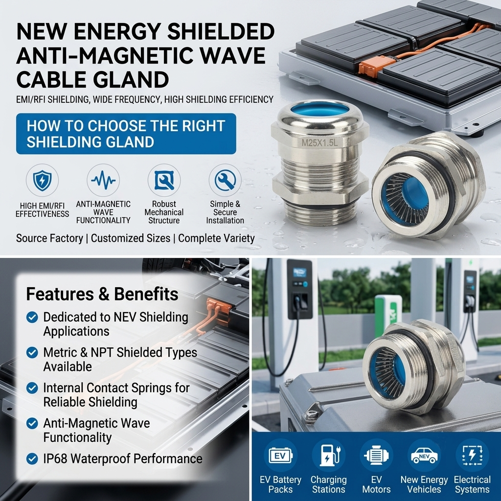
The superior performance of a specialized shielded connector relies on its internal grounding mechanism. Instead of point-contact grounding clips, high-quality shielding glands utilize an internal stainless steel shielding spring or contact iris.
When the gland nut is tightened, this circumferential spring compresses uniformly around the exposed braided shield of the cable. This ensures complete 360-degree electrical continuity across the entire perimeter of the cable braid, minimizing transfer impedance and maintaining an uncompromised Faraday cage configuration across the enclosure wall knockout.
- Standard Glands: Block ingress of water and debris but provide zero electrical bonding for cable shields, allowing high-frequency noise to pass freely through the cutout.
- EMC Shielded Glands: Combine environmental sealing with immediate low-impedance circumferential bonding, turning the cable entry point into an active shielding barrier against electromagnetic waves.
Why EV and Automation Systems Demand Shielded Cable Glands
As industrial machinery and vehicles migrate toward higher voltage thresholds and faster switching topologies, managing electromagnetic interference (EMI) is a strict operational safety requirement rather than an optional design enhancement.
Mitigating Magnetic Waves in Electric Vehicle Powertrains
The deployment of an EV shielded cable gland is an established design practice within modern electric vehicle powertrains. EV traction systems routinely run on 400V to 800V DC buses, utilizing fast-switching insulated-gate bipolar transistors (IGBTs) or silicon carbide (SiC) metal-oxide-semiconductor field-effect transistors (MOSFETs) within the inverter.
The rapid voltage rise times ($dV/dt$) generated by these components create intense electromagnetic noise across adjacent low-voltage wiring harnesses. Utilizing an EV shielded cable gland on the high-voltage lines feeding the electric motor prevents these transient currents from distorting the low-voltage communication signals of safety-critical systems, including advanced driver-assistance systems (ADAS) and battery management systems (BMS).
Protecting Sensitive Signals in High-Frequency Automation
Within modern manufacturing facilities, multi-axis servo motors, CNC machinery, and high-frequency robotic welding units generate severe industrial EMI fields. Standard plastic cable entries fail to protect internal programmable logic controllers (PLCs) from this localized environmental noise.
Deploying a heavy-duty brass nickel-plated EMC gland on sensor and encoder feedback lines shields weak analog and digital signals from nearby power transmission lines. This suppresses data packet corruption and prevents costly unexpected machinery downtime.
Key Selection Metrics: Material, Sealing, and Sizing
Specifying the correct cable gland requires evaluating material chemistry, sealing polymers, and geometric dimensions against the target operating environment.
Brass Nickel-Plated vs. Stainless Steel Glands
Material selection determines both the long-term corrosion resistance and the electrical conductivity of the grounding assembly.
A brass nickel-plated EMC gland is the standard choice for automotive assemblies, commercial charging piles, and factory floor automation. Brass provides excellent inherent electrical conductivity to ensure a low-resistance path for grounding stray currents. The nickel plating adds an outer protective barrier that resists oxidation, galvanic corrosion, and surface wear over extended deployment lifespans.
For extreme processing environments, such as offshore marine platforms, chemical processing plants, or heavy washdown pharmaceutical zones, stainless steel (SS304 or SS316) is specified due to its superior resistance to acids and pitting, though it carries a premium material cost.
Deciphering Thread Specifications: Metric M20 and M25 Systems
Choosing the correct thread sizing ensures mechanical compatibility with enclosure knockouts and matching cable exterior diameters. Engineers frequently source a metric M20 M25 shielded gland assembly to manage mid-range signal, control, and auxiliary power lines.
An M20×1.5 thread typically handles cable outer diameters ranging from 8mm to 14mm, whereas an M25×1.5 thread supports cables from 13mm to 18mm. Selecting the correct size ensures the internal clamping claw applies even radial pressure without over-compressing or damaging the cable jacket.
| Model Number | Metric Thread (M) | Cable Range (Φ mm) | Thread Length (GL mm) | Spanner Size (SW1/SW2 mm) |
| HEMC-MG20-14 | M20 × 1.5 | 8 – 14 | 7 | 24 / 24 |
| HEMC-MG25-18 | M25 × 1.5 | 13 – 18 | 9 | 30 / 30 |
| HEMC-MG32-24 | M32 × 1.5 | 18 – 24 | 11 | 36 / 36 |
| HEMC-MG40-35 | M40 × 1.5 | 28 – 35 | 11 | 50 / 46 |
| HEMC-MG50-38 | M50 × 1.5 | 30 – 38 | 12 | 57 / 55 |
| HEMC-MG63-44 | M63 × 1.5 | 37 – 44 | 12 | 64 / 68 |
- Ingress Protection Rating: Certified IP68 waterproof and dustproof.
- Standard Thermal Limits: -40°C to +120°C (custom configurations support -60°C to +220°C for extreme industrial applications).
Sourcing Reliable Shielded Glands: Direct Factory Benefits
Procuring electrical components for large-scale OEM automotive lines or heavy-industrial infrastructure requires an absolute guarantee of quality uniformity and supply-chain flexibility. Sourcing directly from an established components manufacturer eliminates intermediary distributor markups and grants direct access to specialized engineering support.
For projects requiring non-standard thread lengths, specialized internal clamping dimensions, or custom high-temperature sealing materials, partnering with a manufacturer provides scalable OEM/ODM technical customization to meet precise blueprint tolerances.
To streamline procurement and secure long-term component stability, you can source the industrial-grade New Energy Shielded EMC Gland (M20-M63) from Wenzhou Xingwei Electrical Co., Ltd.. This direct factory access provides competitive wholesale pricing alongside batch-testing documentation to ensure strict compliance with global technical and regulatory standards.
Common Installation Pitfalls That Ruin EMC Shielding
Even the highest-grade shielding hardware fails if installed incorrectly. Avoiding common field installation errors ensures long-term operational reliability.
Inadequate Shielding Spring Contact
The most common field error involves incorrect stripping of the outer cable insulation jacket. If the outer jacket is stripped too far back, or if the copper braided shield is cut unevenly, the internal stainless steel spring cannot establish full 360-degree contact with the braid. This discontinuity breaks the low-impedance path to ground, leaving the system vulnerable to high-frequency noise interference.
Improper Torque Leading to IP68 Seal Failure
Achieving a true IP68 waterproof shielded cable connector rating requires precise tightening torque. Over-tightening the compression nut crushes the internal silicone O-ring and sealing sleeve, causing material deformation and micro-tears that compromise the ingress protection barrier. Conversely, under-tightening leaves small gaps that allow moisture to enter under pressure and allows continuous mechanical vibrations to loosen the connection over time.
Frequently Asked Questions About Shielded Cable Glands (FAQ)
Q1: What is the primary difference between a standard cable gland and an EMC shielded cable gland?
A: A standard gland provides structural strain relief and environmental sealing but leaves the cable shield ungrounded at the entry point. An EMC shielded gland contains an internal conductive element, such as a stainless steel spring, that creates a continuous 360-degree grounding connection with the cable braid to suppress electromagnetic interference.
Q2: Why is an EV shielded cable gland critical for electric vehicle powertrains?
A: EV powertrains use high-voltage inverters that switch current at high frequencies, generating severe electromagnetic fields. An EV shielded cable gland safely grounds these high-frequency emissions to prevent them from radiating into low-voltage communication wires, protecting safety-critical systems from data corruption.
Q3: Does a brass nickel-plated EMC gland provide sufficient corrosion resistance?
A: Yes, the nickel-plating layer over the brass substrate provides excellent protection against atmospheric oxidation, humidity, and mild chemical exposure. It preserves both the structural integrity and the surface electrical conductivity necessary for stable EMC grounding over long operational lifespans.
Q4: How does an IP68 waterproof shielded cable connector maintain its seal under heavy vibration?
A: It utilizes an integrated mechanical clamping claw mechanism combined with high-elasticity silicone seals. The claw evenly distributes pressure around the cable sheath, preventing axial displacement or rotational loosening caused by sustained structural vibrations.
Q5: Can these metric shielded glands be customized for extreme temperature parameters?
A: Yes, while standard configurations operate reliably from -40°C to +120°C, direct factory sourcing allows for the substitution of specialized internal sealing components to extend the thermal operating envelope from -60°C up to +220°C for custom industrial deployments.
Conclusion
Selecting the correct shielding hardware requires balancing electrical continuity, mechanical sizing, and material science. For modern electric mobility and automated manufacturing, omitting proper EMC grounding leads to high warranty costs and catastrophic signal failures. Prioritizing direct factory components with verified technical specifications protects your system from complex EMI diagnostics down the road.
Need specific technical drawings, step-files, or a wholesale quote for your production line? Reach out to our engineering support team at Wenzhou Xingwei Electrical to receive full technical catalogs and customized OEM/ODM options tailored to your project dimensions.