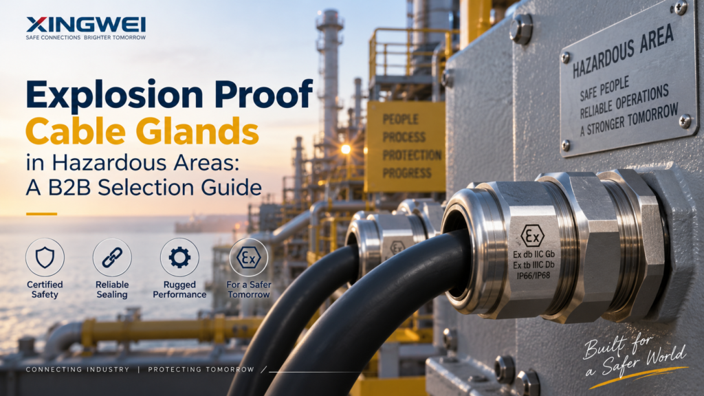
A cable gland that passes routine inspection in a warehouse will fail a hazardous area audit, and the difference is rarely the seal or the material. It is the certification behind the part, and the way that part was matched to the enclosure it feeds. An explosion proof cable gland is a certified cable entry device built to hold an enclosure’s protection concept under fault conditions: contain an internal ignition, keep a flammable atmosphere out of the termination chamber, and hold the cable mechanically sound for the life of the plant.
Procurement teams tend to file it as a low-value line item. Project engineers know better, because a mismatched gland voids the protection concept of an enclosure that may have cost a hundred times more. The decisions below follow the order a specification normally takes: zone classification first, then the Ex marking, then compression type, certification documents, sizing, material and seal, and finally the installation checks that decide whether any of it holds in the field.
What an Explosion Proof Cable Gland Actually Does
A standard cable gland has two jobs. It grips the cable so the conductor termination is not carrying mechanical load, and it seals the enclosure entry against dust and water. Both matter, and neither one is what makes a gland suitable for a hazardous area.
The third job is containment. In an Ex d installation the gland is part of the enclosure’s flameproof path. If a flammable gas enters the enclosure and ignites — a contactor arc, a loose terminal, a short — the internal explosion has to vent through a controlled flame path that cools the gases below ignition temperature before they reach the surrounding atmosphere. The gland’s entry thread, sealing arrangement and compression nut form part of that path. Substitute a cheaper uncertified part and the flame path is no longer the one that was tested.
There is a second consequence that buyers miss. A gland’s rating holds only when it matches the enclosure’s marking. A gland marked Ex db IIC Gb fitted to an Ex e enclosure does not upgrade the enclosure and does not satisfy the Ex e protection concept. The two have to be specified together, as one assembly.
Take an offshore gas platform in the North Sea. The Ex d junction boxes on the wellhead deck carry Ex db IIC Gb glands sized for the armored cable feeding each instrument loop. When the platform is later re-instrumented and a contractor substitutes a general-purpose IP68 gland on two of those boxes, the boxes themselves are still certified, but the installation no longer is. The non-conformance lands on the operator at the next verification audit, not on the contractor who created it.
An explosion proof cable gland is a certified cable entry device that secures and seals a cable where it enters an enclosure in a hazardous area. Unlike a standard gland it must preserve the enclosure’s protection concept, maintain a flameproof path where one is required, and provide strain relief, earthing continuity and ingress sealing as part of the same assembly.
Hazardous Area Classification: Where a Gland Is Required
The question of whether a gland needs certification is answered by the area classification drawing, not by the buyer’s judgement. Two classification systems define those areas, and the export market uses both of them, often on the same project.
Gas Zones, Dust Zones and What Each One Demands
Gas areas are graded by how often a flammable atmosphere is present. Dust areas follow the same logic with different numbering.
| Zone (gas) | Atmosphere present | Minimum EPL | Typical location |
| Zone 0 | Continuously, or for long periods | Ga | Inside a tank vapour space |
| Zone 1 | Occasionally during normal operation | Ga or Gb | Pump seals, sample points, valve stems |
| Zone 2 | Unlikely, and only briefly if it occurs | Gc | Areas adjacent to a Zone 1 boundary |
| Zone (dust) | Atmosphere present | Minimum EPL | Typical location |
| Zone 20 | Continuous cloud of combustible dust | Da | Inside a silo or mill duct |
| Zone 21 | Occasionally during normal operation | Db | Bagging stations, filling heads, transfer points |
| Zone 22 | Unlikely, and only briefly | Dc | Areas adjacent to a Zone 21 boundary |
Cable glands rarely sit in Zone 0 or Zone 20, because the enclosure wall is normally outside the tank or duct that creates the atmosphere. The practical specification for most projects therefore lands on Zone 1 and Zone 2 for gas, and Zone 21 and Zone 22 for dust. What matters is that the gland carries an Equipment Protection Level at least as high as the zone requires.
A flour mill makes the dust case clearly. The interior of the milling duct is Zone 20, but the gland is installed on the outside wall of a motor terminal box in the milling hall, which the classification drawing puts at Zone 21. A Db-rated gland is correct there. A Db gland is also correct on the Zone 22 packing line downstream, because a higher EPL always satisfies a lower zone. Specifying the same part number across both areas is legitimate, provided the certificate’s scope covers it.
Hazardous areas are classified by how often a flammable atmosphere is present. Gas areas run Zone 0 (continuous), Zone 1 (occasional during normal operation) and Zone 2 (unlikely and brief). Dust areas run Zone 20, 21 and 22 on the same logic. The zone sets the minimum Equipment Protection Level that a cable gland must carry.
ATEX Zones and North American Class/Division: Reading Both Systems
European practice comes from the ATEX directives: Directive 2014/34/EU governs the equipment itself, while Directive 1999/92/EC governs the workplace and produces the zone drawing. North American practice comes from the National Electrical Code, which carries two parallel systems. Article 500 uses Class and Division; Article 505 uses the Zone system; Article 506 covers dust.
Class I means flammable gas or vapour, Class II means combustible dust, and Class III means ignitable fibres. Division 1 covers conditions that exist during normal operation, which corresponds broadly to Zone 1, while Division 2 covers conditions that occur only under fault, corresponding broadly to Zone 2. The correspondence is approximate rather than a legal equivalence, and the authority having jurisdiction makes the final call on the installation. When a European panel is destined for a Texas refinery, the enclosure and the gland both need marking the local inspector recognises.
Gas Groups and Temperature Classes
Gas groups describe how easily the atmosphere ignites. Group IIA covers propane and similar gases, IIB covers ethylene, and IIC covers hydrogen and acetylene. The letters get harder as they advance, so a gland rated for IIC covers IIA and IIB as well. Buying IIC across a project removes a whole class of selection error, at a small cost premium.
Temperature classes are separate from the gas group and frequently confused with it. T1 allows a maximum surface temperature of 450 °C, T2 allows 300 °C, T3 allows 200 °C, T4 allows 135 °C, T5 allows 100 °C and T6 allows 85 °C. The class limits the surface temperature of the equipment, not the ambient rating of the gland’s seal. A gland whose silicone seal is rated from −60 °C to +100 °C can still be perfectly correct on a T6 installation, because the seal temperature range and the surface temperature class answer different questions. Both have to be satisfied.
Decoding the Ex Marking on a Cable Gland
Every certified gland carries a marking string, and the string is the specification. Reading it takes about thirty seconds once the position of each element is known.
Reading Ex db IIC Gb Left to Right
| Element | Meaning |
| Ex | The equipment is built to an explosion protection standard |
| d | Protection concept: flameproof enclosure, per IEC 60079-1 |
| b | Equipment Protection Level for that concept — b indicates high protection |
| IIC | Gas group — covers hydrogen and acetylene, the most easily ignited group |
| Gb | Overall EPL: G for gas atmosphere, b for high protection level |
Markings are frequently compound. A gland marked Ex db IIC Gb / Ex eb IIC Gb / Ex tb IIIC Db is certified for flameproof and increased safety use in gas areas and for dust protection by enclosure in dust areas. Note the switch from IIC to IIIC: the first I denotes a gas group, the second denotes a dust group. A single part number covering both is common and convenient, provided the certificate scope lists all three markings.
Ex db, Ex eb and Ex tb: Three Protection Concepts, Three Use Cases
| Concept | Standard | Principle | Zones | Typical use |
| Ex d (db) | IEC 60079-1 | Flameproof enclosure — contains an internal explosion and cools gases through a flame path | 1, 2 | Motors, switchgear, junction boxes containing arcing parts |
| Ex e (eb) | IEC 60079-7 | Increased safety — no arcs or sparks in normal operation, with increased creepage and clearance | 1, 2 | Terminal boxes and enclosures with no arcing components |
| Ex t (tb) | IEC 60079-31 | Protection by enclosure — dust-tight, with limited surface temperature | 21, 22 | Dust handling, bagging, milling, grain and powder processing |
Intrinsically safe circuits deserve a separate note. An Ex ia circuit is safe by energy limitation, but the enclosure housing the terminations is still certified equipment, and the gland still has to be certified for it. Contractors occasionally treat an IS loop as exempt from cable entry requirements. It is not.
For the narrower comparison of flameproof and increased safety entries, and how the two are selected against the same enclosure marking, the Ex d vs Ex e protection concepts walk through the decision in more detail.
An Ex marking reads as a sequence: the word Ex, the protection concept letter (d for flameproof, e for increased safety, t for dust protection by enclosure), the EPL letter, the gas or dust group, and the overall Equipment Protection Level. Ex db IIC Gb therefore means flameproof construction, suitable for hydrogen-group gases, at high protection level, in a gas atmosphere.
Armored or Unarmored: Which Compression Type Fits the Cable
Compression type follows the cable, not the enclosure. Get this backwards and the gland can be certified, correctly sized, and still wrong for the installation it is going into.
Unarmored cable needs a single compression gland. It grips the outer sheath and seals it. The construction is simpler, the cost is lower, and for an Ex e terminal box on a multi-core flexible cable it is the correct choice.
Armored cable needs double compression, and the reason is not mechanical strength. It is gas migration.
Why Double Compression Is Mandatory on SWA and STA Cable
In a steel wire armored or steel tape armored cable, the space between the cores, the fillers and the bedding is not solid. It is a continuous void running the length of the cable. If a flammable atmosphere enters that void at a damaged point somewhere along the run, it can travel inside the cable and arrive at the termination, which sits inside the enclosure. A single compression gland seals only the outer sheath, so it does nothing to stop that path.
A double compression gland seals twice. The outer seal grips the outer sheath. The inner seal, compressed against the inner bedding after the armor has been stripped back, closes the void directly around the cores. Between the two seals, a dedicated armor clamping cone grips the steel wire or tape and maintains mechanical and earth continuity.
| Criterion | Single compression | Double compression |
| Outer sheath sealing | Yes | Yes |
| Inner bedding sealing | No | Yes |
| Armor clamping | Basic mechanical grip | Dedicated armor clamping cone and lockring |
| Gas migration along the cable | Not blocked | Blocked at the inner seal |
| Suitable cable construction | Unarmored | SWA, STA, wire braid |
| Typical hazardous area use | Ex e terminal boxes | Ex d flameproof entries |
The XingWei double compression explosion proof cable glands (BDM-VII/D) are built on exactly this dual-seal arrangement, with a silicone inner and outer seal, a machined armor cone for SWA, STA and braided cable, and a body in nickel-plated brass with 304 or 316 stainless available. Where the cable range has to be matched against armor thickness rather than outer diameter alone, the sizing an explosion proof armored cable gland kit guide carries the full measurement method and the size matrix.
Consider a refinery unit where a four-core SWA feeder runs from a substation to a flameproof motor junction box two hundred metres away. The gland at the motor is correctly sized and correctly marked. If it is a single compression type, the inner bedding is open, and a hydrocarbon leak anywhere along that two hundred metre run has a direct path into a certified enclosure. This is why the double compression requirement is written into the specification rather than left to the installer.
Certification Documents a Buyer Should Demand
Once the zone and the marking are settled, the next question is not technical. It is what the supplier can put on paper, and whether the name on that paper is the party actually manufacturing the part.
ATEX, IECEx, UKCA and UL: What Each Certificate Covers
| System | Region | Legal status | What it establishes |
| ATEX | EU / EEA | Mandatory by law under Directive 2014/34/EU | The product may be placed on the EU market for use in explosive atmospheres; Category 1 and 2 equipment requires a Notified Body |
| IECEx | International | Voluntary, but widely required by buyers and by some national regulators | Certification issued under the IECEx System against the IEC 60079 series; recognised in Australia and accepted as evidence in many other markets |
| UKCA | Great Britain | Mandatory for the GB market | The UK equivalent of CE marking for explosive atmosphere equipment |
| UL / CSA | North America | Required by the authority having jurisdiction and by the NEC | Listing or classification to the relevant UL or CSA standard, with Class/Division or Zone marking |
Two traps sit inside this table. The first is that CE marking is not ATEX. CE covers several directives at once, including EMC and low voltage, and a supplier describing a gland as “CE certified for hazardous areas” is usually describing something other than explosive atmosphere compliance. Ask specifically for the ATEX certificate, with its number and issuing body. The second trap is age. The IEC 61241 series for combustible dust was withdrawn and replaced by IEC 60079-31, so a certificate that still cites IEC 61241 needs its date and its scope checked before it is accepted on a new project.
Ingress protection is a separate specification that runs alongside the Ex marking rather than inside it. For an explanation of how IP66 and IP68 differ and which one a given installation actually needs, the what IP ratings mean and which you actually need article covers the rating system and the common overspecification.
The Document Package to Request Before You Approve a PO
A certificate reference on a datasheet is not a certificate. The document set below is what allows a procurement team to release a purchase order without creating a compliance exposure later.
- Certificate of Conformity or EC-Type Examination Certificate, showing the certificate number and the issuing Notified Body or ExCB.
- The certificate’s scope schedule. This lists the models and thread sizes covered. A certificate covering M20 does not automatically cover M25.
- IECEx Certificate of Conformity, if IECEx is claimed, with its own certificate number.
- Manufacturer’s Declaration of Conformity, naming the legal manufacturer.
- Datasheet stating the Ex marking, IP rating, operating temperature range, cable range and thread form.
- Material and seal compound statement — body material and grade, and the seal compound (silicone, NBR or FKM).
- Ingress protection test evidence, where the IP rating is a project requirement rather than a default.
- Traceability — a batch or heat reference linking the delivered goods to the certificate.
The certificate belongs to the manufacturer, not the distributor. When buying through a trader, ask whose name appears on the certificate and confirm the part you are receiving is inside the certificate’s scope. Our own explosion proof cable gland range ships with the model-level documentation described here, and the certificate for a specific model and thread size should always be checked against the actual document rather than a datasheet line.
ATEX is the mandatory European legal framework for equipment used in explosive atmospheres, while IECEx is a voluntary international certification built on the same IEC 60079 standards. A CE mark on its own is not evidence of ATEX compliance, because CE covers several directives at once. For North America, UL or CSA listing against the NEC applies instead, using Class/Division or Zone marking.
Sizing: The Four Measurements That Decide the Model
A gland one size out will either crush the cable or fail to seal it, and the answer lives in the published cable range rather than in the model number. Four measurements settle the selection.
Cable OD, Inner Bedding, Armor Thickness and Entry Thread
The cable outer diameter sets the size for an unarmored cable on its own. The gland’s outer sealing range must bracket the measured OD with some margin at both ends, because a cable at the very top of a range leaves the seal no room to compress.
The inner bedding diameter matters only for double compression glands, and it is measured after the armor has been stripped back. It is usually the deciding measurement on an armored cable, because the inner range is narrower than the outer range.
The armor wire diameter or tape thickness has to match the clamping cone. Steel wire armor on an M20 gland typically runs between 0.9 mm and 1.25 mm, and a cone sized for that range will not grip a heavier wire properly.
The entry thread is a property of the enclosure, not the gland. Read it off the enclosure’s marking or drawing before ordering anything.
| Gland size | Entry thread | Inner bedding range (mm) | Outer sheath range (mm) | Armor wire (mm) |
| M20s | M20 × 1.5 | 6.1 – 11.6 | 10.2 – 15.8 | 0.9 – 1.25 |
| M20 | M20 × 1.5 | 8.5 – 13.8 | 13.5 – 20.0 | 0.9 – 1.25 |
Sizes from M25 upward follow the same format, with the ranges widening as the thread grows. Because cable tolerances vary between manufacturers, the practical rule is to measure the actual cable with a caliper and match the result against the gland range, rather than working from the nominal figure printed on the cable drum.
Thread Standards: Metric, PG, NPT and G (PF)
Four thread families appear on hazardous area equipment, and they are not interchangeable.
Metric threads such as M20 × 1.5 and M25 × 1.5 dominate outside North America and are the default on most new equipment. PG threads, including PG7, PG9, PG13.5, PG16 and PG21, are a legacy German standard still widespread on older European machinery. NPT is a tapered American pipe thread that seals on the thread itself. G, sometimes written PF, is a parallel British pipe thread that seals on a washer or O-ring against a machined face rather than on the thread.
That last distinction causes more field failures than any other thread issue. A G-thread gland fitted into an NPT entry, or installed without its sealing washer, will thread partway in and appear to seat while providing no seal at all, and the enclosure thread is usually damaged in the process. Where a project mixes European and American equipment, confirm the thread form on each enclosure individually. The Metric, PG and NPT thread standards compared guide sets out the full comparison.
The nickel-plated brass BDM-I/D series is available in Metric, NPT and G threads, with custom thread lengths for thick-walled cast enclosures, which covers the mixed-standard cases that come up on retrofit work.
Sizing an explosion proof cable gland needs four measurements: the cable outer diameter, the inner bedding diameter under the armor, the armor wire or tape thickness, and the enclosure entry thread. All four must fall inside the gland’s published ranges. Measuring with a caliper on the actual cable avoids the tolerance errors that come from working off nominal datasheet figures.
Materials and Seals: Brass, Stainless Steel and Three Seal Compounds
The body material and the seal compound solve two different problems, and buyers regularly optimise one while ignoring the other. A 316 stainless body with the wrong seal will fail in a solvent atmosphere just as surely as a plated brass body will fail in a chloride one.
Nickel-Plated Brass, 304 and 316 Stainless Steel
| Material | Corrosion resistance | Typical atmosphere | Relative cost | Notes |
| Nickel-plated brass | Good | Indoor panels, refineries, mild chemical exposure | $ | Holds a thread well and takes a torque cycle without cracking; the standard choice for high-volume hazardous area work |
| 304 stainless steel | Very good | Offshore, marine, washdown, food and pharmaceutical | $$ | Higher mechanical strength and better pull-out resistance than brass |
| 316 stainless steel | Excellent | Chlorides, acids, salt spray, coastal and subsea | $$$ | Specify where pitting or crevice corrosion is a realistic risk |
Nickel plating protects the brass against atmospheric corrosion and chemical washdown, but it is not a barrier against strong acids or chlorides. In a chlorinated or acidic atmosphere the correct answer is 316, not plated brass with a heavier coating.
The 304 stainless steel XW-BT explosion proof gland illustrates the trade-off in practice: a 304 body with a PA66 flame-retardant claw and NBR seals, IP68 rated for continuous submersion, and available with silicone or FKM seals where the standard compound will not survive the atmosphere. Optional seal grades on a standard body often solve a corrosion problem at far lower cost than moving the whole assembly to a higher alloy.
NBR, Silicone and FKM: Matching the Seal to the Atmosphere
| Seal compound | Temperature range | Resists | Avoid |
| NBR (nitrile) | −40 °C to +100 °C | Water, oils, general industrial atmospheres | Ketones, strong acids, long-term ozone and UV exposure |
| Silicone | −60 °C to +100 °C, with some grades higher | Wide thermal cycling, water, ageing | Some hydrocarbon solvents and concentrated acids |
| FKM (fluororubber) | −20 °C to +200 °C | Acids, solvents, aggressive chemicals, high heat | Ketones, esters, and hot water or steam in some grades |
The temperature range shown against a seal compound is not the temperature class of the installation. A T6 classification limits the equipment’s surface temperature to 85 °C and has nothing to do with whether the seal can survive the process ambient. Both constraints apply, and they are read from different lines of the datasheet.
A chlor-alkali plant shows why the seal decision deserves its own line in the specification. Chlorine and caustic service attacks both the plating and the standard nitrile seal, so the correct specification moves to a 316 body with an FKM seal, even though the temperature is unremarkable and plated brass would have been cheaper. For the narrower comparison of material behaviour across the full gland range, the nickel-plated brass explosion proof gland selection guide sets out the marking and material logic side by side.
Installation and Inspection Points That Decide Compliance
Everything up to this point can be correct and the installation can still fail verification. Most hazardous area non-conformances on cable entries are installation faults rather than product faults, and they share a common signature: they are invisible until someone opens the box.
Five Field Mistakes That Break the Protection Concept
A missing or incorrect earth tag. The armor has to be bonded to the enclosure earth, both for fault current and for equipotential bonding on Ex d equipment. An earth tag left off during a fast shutdown is a straightforward non-conformance with a safety consequence.
No shroud or sealing washer on an Ex d entry. On many Ex d entries the shroud or sealing washer is part of the tested arrangement. Omitting it changes the assembly that the certificate covers.
Under- or over-torquing the compression nut. Under-torque leaves the elastomer uncompressed and the IP rating unachieved, which is the mechanism behind most water ingress found during inspection. Over-torque splits the seal or strips the entry thread, and the damage is usually permanent.
Mixing thread forms. A G-thread gland forced into an NPT entry, or sealed without its washer, damages the enclosure thread and destroys the seal in the same operation.
Reusing or substituting a gland during a shutdown. This is the most expensive of the five, because it survives commissioning and only surfaces at the next verification audit, which then triggers a plant-wide review of every cable entry rather than a single correction.
A panel shop building Ex e control panels for an Italian refinery runs a first-article inspection on the first enclosure of every batch. The check that catches the most faults is not the torque wrench. It is comparing the gland marking on the finished panel against the enclosure marking on the drawing, and confirming the certificate number recorded in the loop file matches the part that was actually fitted. Both checks take under a minute per panel and catch errors that would otherwise reach the site.
Frequently Asked Questions
What is the difference between an explosion proof cable gland and a standard cable gland?
A standard gland grips and seals. An explosion proof cable gland does those two jobs and also preserves the enclosure’s protection concept, which means it is certified to an Ex standard and carries a marking such as Ex db IIC Gb. It uses a heavier construction, a flameproof entry arrangement where the concept requires one, and materials and seals selected for the atmosphere. A standard gland cannot be substituted even when the IP rating appears identical.
Do I need an Ex d or an Ex e cable gland for a Zone 1 area?
Both can be used in Zone 1, and they are not interchangeable. The gland has to match the enclosure it feeds. An Ex d enclosure containing arcing components takes an Ex d entry, while an Ex e enclosure with no arcing parts takes an Ex e entry. The protection concept belongs to the assembly, so the zone alone does not decide it. Read the enclosure marking first, then match the gland to it.
Can a single compression gland be used on armored cable in a hazardous area?
Not where the installation depends on the gland to block gas migration along the cable. A single compression gland seals only the outer sheath, so a flammable atmosphere that enters the cable at a damaged point can travel through the interstices between the cores and reach the enclosure. A double compression gland seals the inner bedding as well, closing that path, and adds a dedicated armor clamping cone for mechanical and earth continuity.
What is the difference between ATEX and IECEx certification for cable glands?
ATEX is the mandatory European legal framework under Directive 2014/34/EU, required to place equipment on the EU market. IECEx is a voluntary international certification scheme built on the same IEC 60079 standards, recognised across many markets including Australia. The technical requirements overlap heavily, but the certificates are separate documents with separate numbers. A CE mark on its own does not demonstrate ATEX compliance.
How do I choose the right size explosion proof cable gland?
Measure four things: the cable outer diameter, the inner bedding diameter under the armor, the armor wire or tape thickness, and the enclosure entry thread. Match all four against the gland’s published ranges, using a caliper on the actual cable rather than the nominal datasheet figure. On armored cable the inner bedding range usually decides the model, because the outer sheath range is wider. Confirm the thread form as well, since Metric, PG, NPT and G are not interchangeable.
A cable gland is a small part of a project and a large part of whether that project passes verification. Once the zone classification is known, the Ex marking tells you which protection concept applies, the cable construction tells you single or double compression, and the certificate package tells you whether the supplier can stand behind the part. Zone, marking, compression, certificate — those four pieces of vocabulary are what turn a catalogue enquiry for an explosion proof cable gland into a specification. If the marking on your enclosure and the marking on the gland you have been quoted do not match, the cable gland team can work through the selection with you before the order is released, and certificates for the specific model and thread size should always be checked against the actual document before a purchase order is placed.