
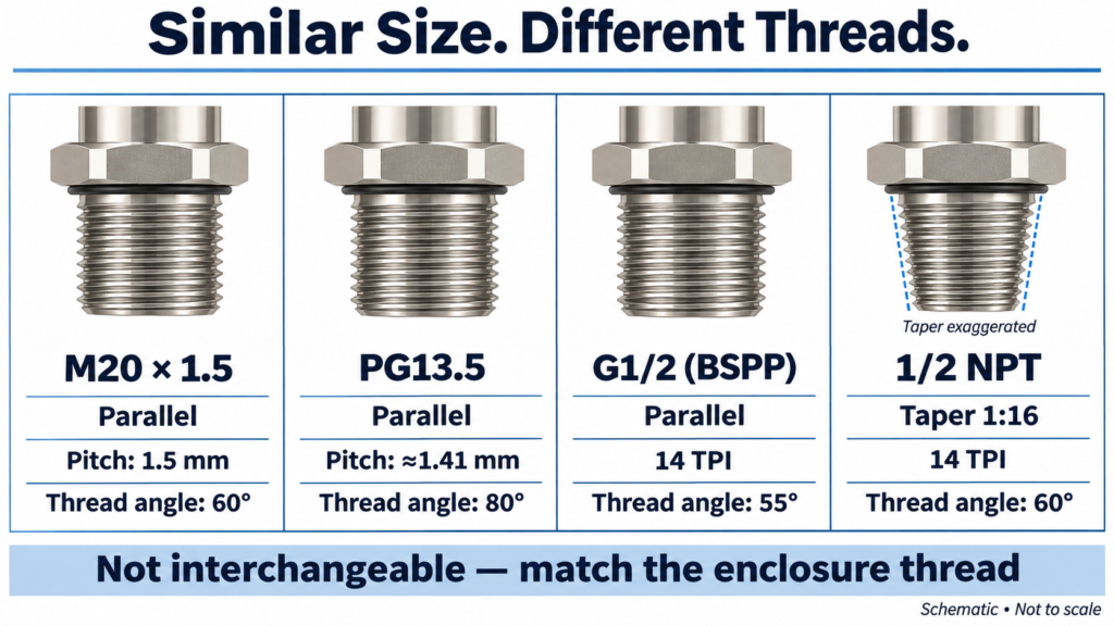
An M20, a PG13.5, a G1/2 and an NPT1/2 all want a hole within about a millimetre of each other. That single coincidence causes more rework on panel builds than any other dimension in the gland world, because the four are not interchangeable and the difference is not visible once the gland is in the box.
This cable gland size chart sets the four thread standards side by side: thread outside diameter, clamping range, thread length and spanner size, taken from the current XingWei catalogue. It also works backwards, so you can start from a measured cable diameter instead of a thread size.
Why Four Threads All Want a 20 mm Hole
| Thread | Thread O.D. | Pitch | Taper | Cable range |
| M20 × 1.5 | 20.0 mm | 1.5 mm | Parallel | 6–12 mm |
| PG13.5 | 20.4 mm | 1.41 mm | Parallel | 6–12 mm |
| G1/2 (BSPP) | 20.9 mm | 1.814 mm | Parallel | 6–12 mm |
| NPT1/2 | 21.2 mm | 1.814 mm | 1:16 tapered | 6–12 mm |
Four threads, four different outside diameters, four different pitches, one nearly identical hole. The clamping ranges match exactly, which is what makes the confusion so easy: all four accept the same cable, so the wrong one feels right until you try to thread it in.
What the thread O.D. column tells you
The thread outside diameter is your starting point for hole size. It is the major diameter of the thread, so the hole cannot be smaller than that figure minus the thread’s tolerance — and for a gland that has to sit flat against a panel, it should be a clearance fit, not an interference one.
For metric, PG and G threads, add a small clearance to the O.D. For NPT, the calculation changes, and the next section explains why.
Why you cannot re-tap one to the other
M20 × 1.5 has a 1.5 mm pitch and a 60° thread form. PG13.5 has 1.41 mm and 80°. G1/2 and NPT1/2 share the 1.814 mm pitch and the 60° form, but NPT is tapered at 1:16 while G is parallel — so a G1/2 gland will start in an NPT1/2 hole and then leak, because the thread only contacts over part of its length.
Running a tap through to “make it fit” removes material from the enclosure thread and leaves a joint that will not hold torque. On a painted steel panel that is a cosmetic problem. On a stainless enclosure in a washdown area it is a leak you will chase for months.
The thread outside diameter in a cable gland size chart is the major diameter of the thread, and it sets the minimum hole size. Metric, PG and G threads are parallel and need a clearance fit. NPT is tapered at 1:16, so its hole is not simply the thread O.D. — and no amount of re-tapping makes one thread standard accept another.
Cable Gland Size Chart: Metric (M) Thread
Metric is the default for new equipment in most of the world, and the range below runs from M8 to M100. Thread pitch is 1.5 mm up to M63 and 2.0 mm above that, which is why the largest sizes are marked separately.
| Thread size | Model | Cable range (mm) | Thread O.D. (mm) | Thread length (mm) | Spanner (mm) |
| M8 × 1.25 | BT M8-5 | 2–5 | 8 | 6 | 12/12 |
| M10 × 1.5 | BT M10-6.5 | 3–6.5 | 10 | 6.5 | 14/14 |
| M12 × 1.5 | BT M12-6.5 | 3–6.5 | 12 | 6.5 | 14/14 |
| M12 × 1.5 | BT M12-8 | 4–8 | 12 | 8 | 17/14 |
| M14 × 1.5 | BT M14-8 | 4–8 | 14 | 8 | 17/17 |
| M16 × 1.5 | BT M16-8 | 4–8 | 16 | 8 | 18/18 |
| M16 × 1.5 | BT M16-10 | 5–10 | 16 | 8 | 20/18 |
| M18 × 1.5 | BT M18-10 | 5–10 | 18 | 8 | 20/20 |
| M20 × 1.5 | BT M20-12 | 6–12 | 20 | 8 | 22/22 |
| M22 × 1.5 | BT M22-14 | 10–14 | 22 | 8 | 24/24 |
| M24 × 1.5 | BT M24-14 | 10–14 | 24 | 8.5 | 24/27 |
| M25 × 1.5 | BT M25-14 | 10–14 | 25 | 8.5 | 24/27 |
| M25 × 1.5 | BT M25-16 | 12–16 | 25 | 8.5 | 27/27 |
| M25 × 1.5 | BT M25-18 | 13–18 | 25 | 8.5 | 30/27 |
| M27 × 1.5 | BT M27-18 | 13–18 | 27 | 8.5 | 30/30 |
| M28 × 1.5 | BT M28-18 | 13–18 | 28 | 8.5 | 30/30 |
| M30 × 1.5 | BT M30-18 | 13–18 | 30 | 8.5 | 30/32 |
| M32 × 1.5 | BT M32-22 | 15–22 | 32 | 10 | 35/35 |
| M36 × 1.5 | BT M36-25 | 18–25 | 36 | 10 | 40/40 |
| M40 × 1.5 | BT M40-25 | 18–25 | 40 | 11 | 40/45 |
| M40 × 1.5 | BT M40-30 | 22–30 | 40 | 11 | 45/45 |
| M42 × 1.5 | BT M42-30 | 22–30 | 42 | 11 | 45/45 |
| M47 × 1.5 | BT M47-33 | 25–33 | 47 | 11 | 50/50 |
| M48 × 1.5 | BT M48-33 | 25–33 | 48 | 11 | 50/50 |
| M50 × 1.5 | BT M50-38 | 32–38 | 50 | 12 | 57/57 |
| M54 × 1.5 | BT M54-38 | 32–38 | 54 | 12 | 57/57 |
| M56 × 1.5 | BT M56-38 | 32–38 | 56 | 12 | 57/59 |
| M60 × 1.5 | BT M60-44 | 37–44 | 60 | 13 | 64/64 |
| M63 × 1.5 | BT M63-44 | 37–44 | 63 | 13 | 64/68 |
| M64 × 2 | BT M64-44 | 37–44 | 64 | 13 | 64/68 |
| M72 × 2 | BT M72-52 | 42–52 | 72 | 15 | 78/78 |
| M75 × 2 | BT M75-52 | 42–52 | 75 | 15 | 78/98 |
| M80 × 2 | BT M80-62 | 55–62 | 80 | 15 | 88/88 |
| M88 × 2 | BT M88-70 | 65–70 | 88 | 16 | 94/94 |
| M100 × 2 | BT M100-84 | 78–84 | 100 | 18 | 110/110 |
Reading the model code
The model number carries the thread size and the top of the clamping range, which is enough to identify the part without opening a table. BT M20-12 is a brass gland, M20 thread, clamping up to 12 mm. Where two models share a thread size, the range is what separates them: M25 appears three times, at 10–14, 12–16 and 13–18 mm, all in the same M25 body.
Order codes add the material and the range explicitly: XW-BT-M20x1.5(6-12)-Cu. The bracket is the cable range, so a purchase order written in that form cannot be filled with the wrong variant.
Metric sizes most projects actually use
M16, M20, M25 and M32 cover the majority of industrial panel work, because they span roughly 5 mm to 22 mm of cable. The very small sizes (M8, M10) are mostly for sensors and instrumentation cable, and the sizes above M50 are for power and marine work where the cable is genuinely thick.
Stocking all 35 metric sizes is unnecessary for most distributors. M16, M20, M25 and M32 in two clamping ranges each will handle the bulk of orders.
Cable Gland Size Chart: PG Thread (DIN 40430)
PG threads still appear on European machinery, older German and Italian equipment, and anything specified to DIN practice. The sizes are not metric and do not convert — a PG16 is not an M16, and the two are 6.5 mm apart at the thread.
| Thread size | Model | Cable range (mm) | Thread O.D. (mm) | Thread length (mm) | Spanner (mm) |
| PG7 | BT PG7-6.5 | 3–6.5 | 12.5 | 6.5 | 14/14 |
| PG9 | BT PG9-8 | 4–8 | 15.2 | 8 | 17/17 |
| PG11 | BT PG11-10 | 5–10 | 18.6 | 8 | 20/20 |
| PG13.5 | BT PG13.5-12 | 6–12 | 20.4 | 8 | 22/22 |
| PG16 | BT PG16-14 | 10–14 | 22.5 | 8 | 24/24 |
| PG19 | BT PG19-14 | 10–14 | 25 | 8.5 | 24/27 |
| PG21 | BT PG21-18 | 13–18 | 28.3 | 8.5 | 30/30 |
| PG25 | BT PG25-22 | 15–22 | 32 | 10 | 35/35 |
| PG29 | BT PG29-25 | 18–25 | 37 | 11 | 40/40 |
| PG36 | BT PG36-33 | 25–33 | 47 | 12 | 50/50 |
| PG42 | BT PG42-38 | 32–38 | 54 | 13 | 57/57 |
| PG48 | BT PG48-44 | 37–44 | 59.3 | 14 | 64/64 |
| PG63 | BT PG63-52 | 42–52 | 72 | 15 | 77/77 |
The PG sizes that still turn up on European equipment
PG9, PG13.5 and PG16 are the ones you will meet most often, and PG13.5 is the awkward one — it sits between PG11 and PG16 with no metric equivalent, and its 20.4 mm thread is close enough to M20 to be mistaken for it on a quick measurement.
For a wider treatment of how the standards relate and where each is still specified, the guide to metric versus PG threads covers the history and the conversion traps.
Cable Gland Size Chart: NPT Thread
NPT is the North American standard, and the important difference is the taper. The thread is cut at 1:16, so the outside diameter at the small end is smaller than the figure in the table — that figure is measured at the gauge plane, partway along the thread.
| Thread size | Model | Cable range (mm) | Thread O.D. (mm) | Thread length (mm) | Spanner (mm) |
| NPT1/4 | BT NPT1/4-6.5 | 3–6.5 | 13.6 | 7 | 14/14 |
| NPT3/8 | BT NPT3/8-8 | 4–8 | 17 | 8 | 18/18 |
| NPT1/2 | BT NPT1/2-12 | 6–12 | 21.2 | 8 | 22/22 |
| NPT3/4 | BT NPT3/4-18 | 13–18 | 26.5 | 9 | 30/30 |
| NPT1 | BT NPT1-25 | 18–25 | 33.2 | 11 | 40/40 |
| NPT1¼ | BT NPT1 1/4-33 | 25–33 | 41.9 | 13 | 50/50 |
| NPT1½ | BT NPT1 1/2-38 | 32–38 | 48 | 14 | 57/57 |
| NPT2 | BT NPT2-44 | 37–44 | 60 | 14 | 64/64 |
| NPT2½ | BT NPT2 1/2-52 | 42–52 | 72.6 | 15 | 77/77 |
| NPT3 | BT NPT3-70 | 65–70 | 88.6 | 15 | 94/94 |
NPT is tapered, so the hole is not the thread O.D.
Because the thread tapers, an NPT gland seals partly by wedging into the enclosure thread. That is also why an NPT gland can look seated while only a few turns are engaged: the thread is doing the sealing, and it only does that over the tapered portion.
The practical consequence for hole sizing is that the tapped hole must be produced with the correct NPT tap and checked with a gauge, not drilled to the number in this table and tapped with whatever is in the drawer. If you are converting an existing metric or PG entry to NPT, use an adaptor rather than re-tapping. The guide to metric, PG and NPT thread standards covers the thread forms and where each one is specified.
Cable Gland Size Chart: G (PF / BSPP) Thread
G thread, written PF in older Japanese and Chinese documentation, is a parallel thread to ISO 228. It appears on imported European and Asian equipment and on instrumentation ports.
| Thread size | Model | Cable range (mm) | Thread O.D. (mm) | Thread length (mm) | Spanner (mm) |
| G1/4 | BT G1/4-6.5 | 3–6.5 | 13.1 | 7 | 14/14 |
| G3/8 | BT G3/8-8 | 4–8 | 16.6 | 8 | 18/18 |
| G1/2 | BT G1/2-12 | 6–12 | 20.9 | 8 | 22/22 |
| G3/4 | BT G3/4-18 | 13–18 | 26.4 | 9 | 30/30 |
| G1 | BT G1-25 | 18–25 | 33.2 | 11 | 40/40 |
| G1¼ | BT G1 1/4-33 | 25–33 | 41.9 | 13 | 50/50 |
| G1½ | BT G1 1/2-38 | 32–38 | 47.8 | 14 | 57/57 |
| G2 | BT G2-44 | 37–44 | 59.6 | 14 | 64/64 |
| G2½ | BT G2 1/2-52 | 42–52 | 75.1 | 15 | 77/77 |
| G3 | BT G3-70 | 65–70 | 87.8 | 15 | 94/94 |
Which Gland Fits My Cable? Reverse Lookup
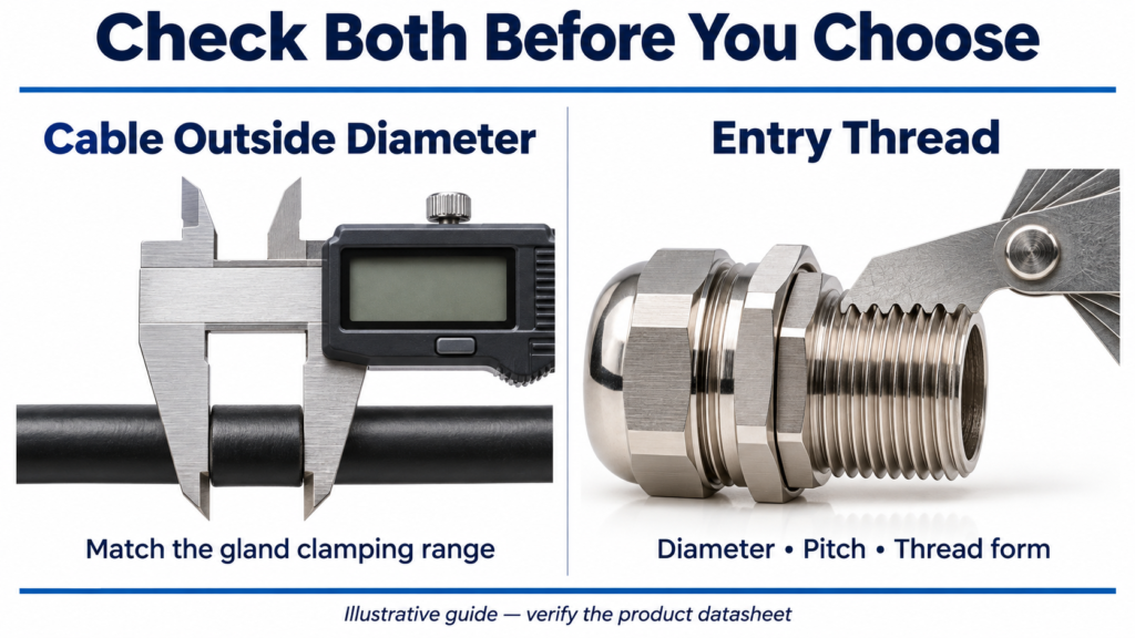
Most selection problems start from the cable, not the thread. Measure the cable’s outer diameter with a calliper — not the conductor size, and not the figure printed on the drum — then use this table.
| Measured cable O.D. | Best fit | Alternative |
| 4 mm | M8 × 1.25 (2–5 mm) | M10 × 1.5 (3–6.5 mm) |
| 6 mm | M12 × 1.5 (4–8 mm) | M14 × 1.5 (4–8 mm) |
| 8 mm | M16 × 1.5 (5–10 mm) | M18 × 1.5 (5–10 mm) |
| 10 mm | M20 × 1.5 (6–12 mm) | M22 × 1.5 (10–14 mm) |
| 12 mm | M22 × 1.5 (10–14 mm) | M24 × 1.5 (10–14 mm) |
| 14 mm | M25 × 1.5 (12–16 mm) | M25 × 1.5 (13–18 mm) |
| 16 mm | M25 × 1.5 (13–18 mm) | M27 × 1.5 (13–18 mm) |
| 18 mm | M32 × 1.5 (15–22 mm) | M25 × 1.5 (13–18 mm) |
| 22 mm | M36 × 1.5 (18–25 mm) | M40 × 1.5 (18–25 mm) |
| 26 mm | M40 × 1.5 (22–30 mm) | M42 × 1.5 (22–30 mm) |
| 30 mm | M47 × 1.5 (25–33 mm) | M48 × 1.5 (25–33 mm) |
| 35 mm | M50 × 1.5 (32–38 mm) | M54 × 1.5 (32–38 mm) |
| 40 mm | M60 × 1.5 (37–44 mm) | M63 × 1.5 (37–44 mm) |
| 45 mm | M72 × 2 (42–52 mm) | M75 × 2 (42–52 mm) |
| 50 mm | M72 × 2 (42–52 mm) | M75 × 2 (42–52 mm) |
| 60 mm | M80 × 2 (55–62 mm) | — |
| 70 mm | M88 × 2 (65–70 mm) | — |
| 80 mm | M100 × 2 (78–84 mm) | — |
Why the widest range is not the best fit
A gland with a 5–10 mm range and a gland with a 13–18 mm range will both accept a 9 mm cable, if the second one is over-compressed past its design. Only the first is a correct selection.
The seal works in the middle of its range. At the bottom of a clamping range the elastomer is barely compressed and the joint weeps under a head of water; at the top it is over-compressed, insertion becomes difficult, and on a nylon dome nut the thread can split on the final turn. Aim for the middle third.
That is why the table above sometimes recommends a larger thread than the obvious one. An 18 mm cable fits an M25 gland at 13–18 mm, but only just — it sits at the very top of the range. M32 at 15–22 mm puts the same cable near the middle, and that is the better engineering choice even though it costs more.
Thread Length, Wall Thickness and Spanner Size
Thread length is the column people skip, and it decides whether the gland can be secured at all.
The thread has to pass through the panel wall, then the locknut, then any sealing washer. If the thread is 8 mm and the panel is 6 mm, you have 2 mm for a locknut — not enough. Cast enclosures are frequently thicker at the entry point than the drawing suggests, so measure the wall at the actual hole.
| Thread length | Panel thickness that leaves room for a locknut |
| 6–6.5 mm | Up to about 2 mm |
| 8 mm | Up to about 4 mm |
| 8.5–10 mm | Up to about 5.5 mm |
| 11–13 mm | Up to about 8 mm |
| 14–15 mm | Up to about 10 mm |
| 16–18 mm | Up to about 12 mm |
Spanner size matters for the same practical reason. The two figures in the table are the across-flats dimension of the body and of the dome nut, which are not always the same — M25 at 13–18 mm needs 30 mm on the body and 27 mm on the nut. On a gland fitted in a recess, that difference decides whether a spanner can reach it at all.
Where the standard thread is too short for the wall, the options are a long-thread variant, an adaptor, or a different entry point. Selecting a longer thread at the ordering stage costs nothing; discovering it on site costs a shutdown.
Where the Sizes Differ by Material
The tables above are the brass BT series. Nylon and stainless ranges are not identical, and the difference is large enough to matter at the selection stage.
Nylon glands typically offer two clamping ranges per thread size, a wide one and a narrow one, so the same M20 body covers either 6–12 mm or 5–9 mm. Stainless bodies tend to carry slightly shorter thread lengths than brass at the same thread size, because the material is stronger and the wall can be thinner.
The practical rule is to read the range from the datasheet for the material you are actually buying, not from a general size chart. The brass, nylon and stainless steel comparison covers which material suits which environment; this page covers dimensions.
For the brass series in the tables above, the nickel-plated brass waterproof cable gland page carries the full range. The nylon equivalent, with the same four thread standards, is listed under IP68 nylon cable glands, and stainless bodies with metric and PG threads under stainless steel cable glands.
Frequently Asked Questions
How do I read a cable gland size chart?
Start from the cable, not the thread. Measure the cable’s outer diameter, find the gland whose clamping range contains that figure with the cable near the middle of the range, then note the thread size in the same row. The thread O.D. column gives you the hole size and the thread length tells you the maximum panel thickness.
What is the difference between M20 and PG13.5?
The thread. M20 × 1.5 has a 20.0 mm outside diameter and a 1.5 mm pitch with a 60° thread form; PG13.5 has 20.4 mm and a 1.41 mm pitch with an 80° form. Both clamp 6–12 mm cable and both want a hole close to 20 mm, but neither will thread into the other’s hole.
Is NPT the same as G thread?
No, although they share a 1.814 mm pitch and a 60° thread form. G thread is parallel; NPT is tapered at 1:16. A G1/2 gland will start in an NPT1/2 hole but will only contact over part of the thread, which is a leak path rather than a joint.
How much bigger than the thread should the hole be?
Enough for a clearance fit — typically a few tenths of a millimetre over the thread outside diameter for metric, PG and G threads, depending on your punch or drilling standard. Too tight and the gland will not seat flat against the panel; too loose and the O-ring has nothing to compress against. NPT is the exception: the hole is tapped, not drilled to the O.D.
Can I use an adaptor instead of a different gland?
Yes, and it is usually the right answer when the enclosure thread is fixed but the cable has changed. An adaptor converts one thread to another in a short body, so an M20 entry can take an M25 gland or a PG16 gland. The trade-off is an extra joint and a slightly longer assembly, which matters in tight enclosures.
A cable gland size chart is only useful if it removes a decision. This one should settle four things before the order goes out: the thread standard from the enclosure, the thread size from the hole, the clamping range from the measured cable, and the thread length from the panel wall.
Get those four and the rest — material, IP rating, seal compound — is a separate conversation. Miss any of them and the gland arrives correct in every respect except the one that matters.
The full brass range across metric, PG, NPT and G threads is listed in the cable gland category, and custom thread lengths are available where a standard body does not reach your panel. For measurement method rather than dimension tables, the cable gland sizing guide covers how to measure a cable and an entry correctly.