High-frequency electromagnetic interference (EMI) is a primary cause of field failures in variable frequency drives (VFDs), solar inverters, and battery energy storage systems (BESS). When switching frequencies leak into nearby control wiring or sensor circuits, the resulting electrical noise causes signal distortion, PLC communication drops, and nuisance fault trips.
Standard IP68 cable glands protect against water and dust ingress, but they leave the electrical enclosure vulnerable to high-frequency electromagnetic radiation. To eliminate noise while maintaining environmental integrity, engineers rely on specialized cable entry systems that bond the cable braid directly to the cabinet ground.
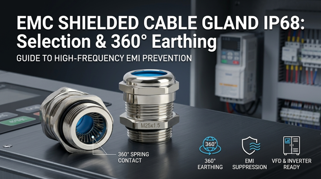
This guide examines how an EMC Shielded Cable Gland IP68 functions, compares 360° spring earthing against traditional pigtail wiring, provides a metric selection matrix, and outlines key installation steps for power electronics applications.
The Hidden Threat of EMI in VFD & Renewable Energy Systems
Modern industrial control panels combine high-voltage power distribution with low-voltage control circuits in tight spaces. Pulse-width modulation (PWM) from VFDs and power conversion systems (PCS) creates severe high-frequency parasitic noise (RFI/EMI). Without a continuous, low-impedance path to ground at the cabinet entry point, this noise radiates into the ambient panel space or conducts through the cable armor.
Unscreened entry points turn shielded cables into antennas. While shielded power cables absorb internal noise, leaving the shield ungrounded—or improperly terminated at the enclosure wall—renders the shielding ineffective.
Furthermore, regulatory frameworks like the EU EMC Directive (2014/30/EU) enforce strict limits on radiated and conducted emissions. Achieving compliance requires terminating every shielded cable passing through a panel wall with a certified, low-resistance grounding cable entry.
How the 360° Shield Contact Mechanism Works in EMC Gland Kits
Traditional grounding techniques often fail at higher frequencies due to elevated transfer impedance. An EMC cable gland solves this by creating a continuous, low-resistance mechanical interface around the entire circumference of the braided shield.
Low-Impedance Earthing via Internal Spring Contacts
Inside a brass nickel plated EMC cable gland 360 degree earthing assembly, a flexible, highly conductive stainless steel or brass contact spring encircles the exposed cable braid. When the compression nut is tightened, this spring compresses uniformly against the braid.
This circumferential contact creates a low-inductance connection across 360 degrees. Unlike point-contact set screws or drain wires, circumferential earthing distributes high-frequency surface currents evenly, keeping transfer impedance below 10 mΩ/m at 100 MHz.
Triple-Layer Defense: Nickel-Plated Body, Locknut & NBR Washer
Achieving electromagnetic compatibility while maintaining long-term outdoor durability requires a coordinated hardware kit:
- Nickel-Plated Brass Body: Provides high mechanical strength, galvanic corrosion resistance, and high electrical conductivity.
- NBR Sealing Washer: Positioned between the entry thread and the panel wall to ensure an IP68 ingress protection rating against water, oil, and industrial dust.
- Star Locknut / Tooth Washer: Cuts through painted or anodized enclosure surfaces to establish direct metal-to-metal continuity with the enclosure plate.
For panel builders requiring a single-source hardware solution, engineered kits like the New Energy Shielded EMC Cable Glands (M20–M63) integrate a brass nickel-plated body, a 360° contact spring, an NBR sealing washer, and a matching locknut to streamline cabinet assembly.
Standard Waterproof Glands vs. EMC Shielded Cable Glands
Engineers frequently evaluate whether standard brass glands can be retrofitted with external ground clamps or if dedicated EMC glands are necessary. The table below highlights the operational differences between standard IP68 glands and 360° EMC shielded entry systems.
| Feature / Parameter | Standard IP68 Brass Gland | 360° EMC Shielded Cable Gland IP68 |
| Shield Termination | None (Requires external pigtail wire) | 360° circumferential spring contact |
| Shielding Attenuation | 0 dB (No noise suppression) | 60–80 dB (up to 1 GHz) |
| High-Frequency Impedance | High (Antenna effect via pigtail) | Low (<10 mΩ/m) |
| Cable Compatibility | Unshielded power & control cables | Braid-shielded (SWA/CY/SY/VFD) cables |
| Ingress Protection Rating | IP68 (NEMA 4X / 6P) | IP68 (NEMA 4X / 6P) |
| Typical Failure Risk | EMI noise coupling, drive trip errors | None (when installed with correct torque) |
Selecting an IP68 EMC cable gland with locknut and NBR washer kit guarantees both environmental ingress protection and electromagnetic noise suppression without requiring extra grounding straps inside the enclosure.
Sizing & Selection Guide: Matching Metric/NPT Threads to Shielded Cables
Selecting the correct gland size requires matching three dimensions: the cable outer jacket diameter, the exposed braid diameter, and the panel knockout thread.
Key Measurement Steps: Inner Sheath, Braid, and Outer Diameter
- Outer Sheath Diameter (OD): Measure the unstripped cable outer jacket. This dictates the sealing range of the outer NBR gland insert.
- Braid Diameter: Strip back the outer jacket by 10–15 mm to measure the overall diameter of the exposed metal braid. The internal contact spring must compress tightly onto this dimension.
- Thread Selection: Match the panel knockout thickness and thread pitch (Metric M12–M63 or NPT 3/8″–2″).
Metric (M20–M63) & NPT Thread Specification Matrix
Below is a reference guide for specifying a waterproof shielded cable gland for VFD and inverter cables:
| Thread Size | Cable Outer Diameter (mm) | Shielding Braid Diameter (mm) | Mounting Hole Diameter (mm) | Enclosure Wall Seal |
| M16 x 1.5 | 4.0 – 8.0 | 2.5 – 6.0 | 16.2 | NBR O-Ring / Flat Washer |
| M20 x 1.5 | 6.0 – 12.0 | 4.0 – 9.5 | 20.3 | NBR O-Ring / Flat Washer |
| M25 x 1.5 | 10.0 – 16.0 | 7.0 – 13.5 | 25.3 | NBR O-Ring / Flat Washer |
| M32 x 1.5 | 14.0 – 21.0 | 11.0 – 18.0 | 32.3 | NBR O-Ring / Flat Washer |
| M40 x 1.5 | 19.0 – 28.0 | 15.0 – 24.0 | 40.4 | NBR O-Ring / Flat Washer |
| M50 x 1.5 | 27.0 – 35.0 | 22.0 – 31.0 | 50.5 | NBR O-Ring / Flat Washer |
| M63 x 1.5 | 34.0 – 44.0 | 29.0 – 39.0 | 63.5 | NBR O-Ring / Flat Washer |
Need sizing verification for specialized cable construction? Contact our technical application specialists to review your cable datasheets and select the optimal thread and spring range for your panel enclosure.
Common Field Installation Errors and How to Avoid Them
Even high-performance hardware fails if installed improperly. Below are four frequent field mistakes encountered during EMC gland installation and instructions on how to ground shielded cable with EMC gland assemblies correctly.
| Field Error | System Impact | Correct Installation Procedure |
| “Pigtail” Braid Grounding | High inductive reactance creates an antenna effect, radiating noise inside the panel. | Strip 10–15 mm of outer jacket; clamp braid directly using the 360° spring inside the gland. |
| Insufficient Outer Stripping | Outer jacket covers braid inside the gland, preventing contact spring engagement. | Measure internal spring position; strip outer sheath so braid aligns precisely with spring contact zone. |
| Painted Enclosure Contact | Paint or powder coating insulates locknut from steel plate, breaking cabinet earth loop. | Use a serrated locknut or remove paint around the mounting hole to ensure metal-to-metal continuity. |
| Omitting NBR Washer | Moisture and dust penetrate entry hole, leading to internal short circuits and IP rating failure. | Always install the NBR washer on the external thread shoulder before inserting through the panel wall. |
Frequently Asked Questions (FAQ)
How does an EMC shielded cable gland achieve 360-degree earthing?
An EMC cable gland contains an internal conductive spring ring that compresses evenly around the stripped cable braid. This 360-degree contact creates a continuous, circumferential earthing connection with extremely low transfer impedance across high frequencies.
Why is an IP68 rating necessary for EMC cable glands in VFD applications?
VFD drives and power conversion enclosures are often deployed in washdown, outdoor, or dusty industrial manufacturing environments. An IP68 rating guarantees that the cable entry point remains completely dust-tight and protected against continuous water submersion.
Can I use a standard brass cable gland for shielded cables if I ground the braid manually?
Manual grounding via a wire pigtail creates high parasitic inductance at frequencies above 10 MHz, turning the drain wire into an antenna. A dedicated EMC cable gland provides 360-degree shielding that attenuates high-frequency noise by up to 80 dB.
What is the difference between Metric (M) and NPT EMC cable glands?
Metric threads (e.g., M20x1.5) feature a straight thread profile designed to be secured with a locknut and sealed with an NBR washer. NPT threads feature a tapered profile that seals via thread deformation, commonly used in North American industrial equipment.
Why is a pigtail ground wire inferior to a 360° EMC cable gland spring contact?
A pigtail ground wire forces high-frequency noise currents through a single narrow conductor, creating high impedance and radiating EMI into nearby panel components. A 360° spring contact distributes current around the entire cable perimeter, dissipating noise effectively to earth.
Conclusion & Technical Selection Steps
Resolving electromagnetic interference in high-power industrial equipment requires a systematic approach to cable entry termination. Using a standard gland with internal pigtail wiring leaves sensitive electronics exposed to high-frequency noise and compromises enclosure reliability.
When selecting an entry solution for VFDs, inverters, or energy storage cabinets:
- Measure the exact cable outer diameter and shield braid thickness.
- Ensure the gland incorporates a 360-degree spring contact mechanism to maintain continuous shield integrity.
- Confirm that the assembly includes an NBR sealing washer and serrated locknut to guarantee both IP68 protection and frame earthing continuity.
By integrating dedicated 360° EMC cable entry kits into panel specifications, engineers eliminate EMI field errors, protect sensitive control circuits, and streamline compliance with international EMC standards.