Water ingress inside outdoor junction boxes and industrial enclosures rarely stems from defective enclosure bodies. In most field operations across coastal plants, solar farms, and marine sites, the primary point of ingress is an incorrectly installed cable entry point. Even an IP68-rated cable gland fails when installation procedures deviate from mechanical tolerance standards.
Preventing moisture entry requires understanding the mechanics of sealing. Small execution errors during cable stripping, gland tightening, or thread mounting break the continuous environmental seal. This guide breaks down the most frequent cable gland installation mistakes, the physical mechanisms behind seal failures, and the exact corrective steps needed to maintain long-term weatherproofing.
The Hidden Cost of Water Ingress in Industrial Enclosures
An IP68 rating certifies that a cable gland withstands continuous submersion under specified pressure conditions during laboratory testing. However, field conditions introduce real-world variables such as temperature fluctuations, continuous vibration, UV exposure, and mechanical stress.
When day-to-night thermal cycling occurs inside a sealed junction box, internal air expands during hot operational hours and cools during shutdown periods. This rapid cooling creates an internal vacuum effect. If a cable gland sealing ring is slightly misaligned or under-torqued, this negative pressure actively draws external moisture and humid air through micro-gaps along the cable sheath or thread entry.
Once water enters, it triggers capillary action, pulling liquid further along internal conductor strands. The result ranges from intermittent short circuits and ground faults to total equipment flashover and costly unscheduled downtime. Maintaining the integrity of the cable gland entry is the most critical factor in protecting internal electronics.
Top 5 Cable Gland Installation Mistakes Disrupting IP68 Protection
Mistake 1: Incorrect Sealing Ring Torque (Over & Under-Tightening)
The elastomeric sealing ring (typically Neoprene or EPDM) relies on precise radial compression against the cable’s outer sheath. Applying improper torque directly compromises this sealing boundary.
- Under-Torquing: Leaving the compression nut loose fails to deform the sealing insert sufficiently around the cable circumference. This leaves open channels for liquid penetration under ambient rain or direct water jets.
- Over-Torquing: Excessive force distorts the elastomeric material beyond its yield point, pushing the seal out of its retention groove or tearing the inner sealing lip. Over-compressed rubber loses its elastic memory and degrades rapidly under UV exposure and heat.
Corrective Action: Always follow the manufacturer’s recommended torque specifications using a calibrated torque wrench rather than applying unmeasured force with pipe wrenches.
| Cable Gland Size | Typical Sealing Nut Torque (Nm) | Recommended Compression Profile |
| M16 / PG9 | 3.5 – 5.0 Nm | Uniform 25% radial seal deformation |
| M20 / PG13.5 | 7.5 – 10.0 Nm | Uniform 25% radial seal deformation |
| M25 / PG21 | 10.0 – 15.0 Nm | Uniform 30% radial seal deformation |
| M32 / PG29 | 15.0 – 20.0 Nm | Uniform 30% radial seal deformation |
Mistake 2: Inaccurate Cable Outer Sheath Stripping Length
Cable glands achieve IP68 sealing by clamping directly onto a uniform, smooth outer cable sheath. Stripping the jacket incorrectly ruins the seal placement:
- Stripping Too Far Back: If the outer sheath is stripped too close to the gland entry, the sealing rubber lands on uneven internal core fillers, armor wires, or unjacketed conductors rather than the smooth outer jacket.
- Uneven Sheath Cut: A jagged or angled cut on the outer sheath leaves micro-gaps inside the sealing chamber where water easily bypasses the compression ring.
Corrective Action: Measure the internal chamber depth of the gland before stripping. Ensure the outer jacket extends completely through the internal sealing ring by at least 5–8 mm past the compression boundary.
Mistake 3: Neglecting Thread Sealing and Box Wall Fit
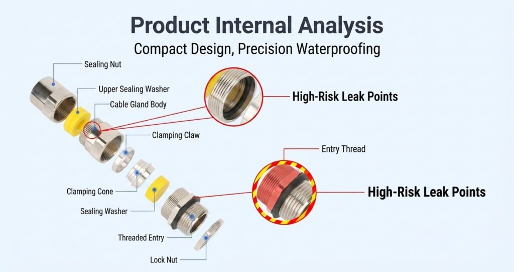
Focusing solely on the cable clamping nut while ignoring the entry thread interface is a common oversight. Water can bypass the main cable seal entirely by creeping around the male mounting thread where it meets the enclosure wall.
- Missing Entry Washer: Installing a metal cable gland directly against an unmachined enclosure wall without a Neoprene, Nylon, or flat sealing washer leaves open pathways through surface roughness.
- Unsealed Clearance Holes: When mounting a gland into an unthreaded clearance hole, failing to apply an O-ring on the outer interface allows water to seep straight past the locknut threads.
Corrective Action: Always install a flat sealing washer or dedicated O-ring between the gland entry shoulder and the outer wall of the enclosure. Ensure the mounting hole surface is flat, clean, and free of burrs.
[ Enclosure Outer Wall ] <--- Sealing Washer / O-Ring <--- [ Cable Gland Body Shoulder ]
Mistake 4: Improper Armor Clamping in Double Compression Glands
When terminating Steel Wire Armored (SWA) or Steel Tape Armored (STA) cables with double compression glands, the internal sealing ring (inner sheath seal) and outer sealing ring must work in tandem.
Field technicians frequently make two critical errors during armor termination:
- Failing to Seat the Armor Cone Correctly: Misaligned armor wires create uneven spacing that prevents the gland body from drawing up fully, leaving the outer sealing ring under-compressed.
- Inverted Armor Clamping Rings: Installing the clamping cone backward distorts the gland geometry, preventing the inner sheath sealing ring from making $360^\circ$ contact around the inner jacket.
Corrective Action: Evenly splay armor wires around the cone ($360^\circ$ coverage) and trim excess wire length before tightening the middle nut. Verify that both inner and outer elastomeric seals seat firmly against their respective jacket layers.
Mistake 5: Excessive Bending Stress and Strain Relief Failure
Cable glands are engineered to provide environmental sealing and moderate axial strain relief. They are not designed to serve as structural elbow supports for heavy, unsupported cables.
When a cable is bent sharply right at the exit point of the gland nut, the lateral pull forces the elastomeric sealing ring to distort unevenly. This creates an oval-shaped gap on one side of the cable outlet, rendering the IP68 seal useless against wind-driven rain or washdowns.
Corrective Action: Maintain a minimum cable bending radius equal to at least 10 times the cable’s overall outer diameter ($10\times\text{OD}$). Install external cable cleats, saddles, or support trays within 300 mm of the gland exit to isolate the sealing junction from mechanical strain.
Cable Gland Installation Errors vs. Waterproof Failure Mechanism
| Installation Mistake | Direct Physical Consequence | Waterproof Rating Impact | Corrective Action Standard |
| Over-Torquing Sealing Nut | Rubber seal extrusion / structural tearing | IP68 degrades to IP54 | Apply measured torque per thread specification |
| Incorrect Sheath Strip Length | Seal clamps onto armor/filler instead of jacket | Complete seal loss at cable core | Verify jacket landing length inside gland body |
| Missing Entry Sealing Washer | Capillary leakage along threads into enclosure | IP Rating failure at enclosure boundary | Install flat Neoprene/Nylon Washer between gland & box |
| Extreme Cable Bending Angle | Radial gap created at sealing rubber outlet | Micro-gaps open under mechanical vibration | Maintain $10\times\text{OD}$ bend radius and add external cable support |
Waterproofing Checklist: How to Prevent Water in Junction Box Cable Entry
Follow this verification process before handing off any electrical installation for commissioning:
- Match Cable Diameter to Clamping Range: Verify with a caliper that the cable’s outer diameter falls squarely within the gland’s specified sealing range (e.g., 9.0–14.0 mm for standard M20).
- Inspect Sealing Components: Confirm the internal rubber seal, entry thread O-ring, and locknut are present and free of debris or cracks.
- Prepare the Cable End: Cut the outer sheath clean and square. Deburr armor wires on SWA cables to prevent seal puncture.
- Assemble Accessories in Order: Slide the PVC protective shroud, locknut, earth tag, and entry sealing washer onto the entry body in correct sequence.
- Tighten to Specification: Tighten the gland entry body firmly against the wall, then torque the outer compression nut until the rubber seal visibly wraps uniformly around the cable sheath.
- Add External Strain Relief: Secure the cable to an adjacent mounting structure to eliminate side-loading tension on the gland outlet.
Choosing High-Tolerance Hardware to Reduce Human Installation Error
While correct installation practices are essential, field conditions are rarely perfect. Tight spaces, extreme weather, and varying installer skill levels increase the risk of manual assembly errors. Choosing cable glands engineered with built-in mechanical tolerances helps offset these human variables.
To minimize installation-related failures, select glands built with high-grade nickel-plated brass or SS316 stainless steel housings featuring precision CNC-machined threads. Look for designs incorporating anti-twist elastomeric seals and wide-clamping claw mechanisms. These features distribute compression evenly across the cable circumference, preventing seal twisting or rubber tearing even if an installer applies slightly higher torque than specified.
For outdoor enclosures, junction boxes, and automation equipment operating in high-humidity or washdown environments, explore engineered Waterproof Cable Glands that integrate pre-fitted entry seals and high-tenacity PA66 clamping inserts for reliable IP68 protection.
Frequently Asked Questions (FAQ)
How do I prevent water ingress in a junction box cable entry?
Ensure the cable outer diameter matches the gland’s clamping range, install a flat sealing washer between the gland shoulder and the box wall, and torque the compression nut until the elastomeric insert forms a uniform $360^\circ$ seal around the cable sheath without over-tightening.
Why does my IP68 cable gland still leak water?
IP68 leaks usually occur due to over-tightening (which tears or distorts the rubber seal), under-tightening, missing thread sealing washers, or bending the cable too close to the gland exit, which pulls the seal open on one side.
What torque should be applied to a cable gland sealing nut?
Torque depends on gland size and material. Standard M20 brass or nylon glands typically require 7.5 to 10.0 Nm of torque. Always refer to the manufacturer’s datasheet rather than over-tightening with unmeasured manual tools.
How do SWA cable gland waterproofing mistakes occur in hazardous areas?
In SWA (Steel Wire Armored) cable glands, leaks often happen when the outer sheath is stripped back too far, leaving the outer seal clamping onto uneven armor wire instead of the smooth outer jacket, or when the inner sheath seal is omitted during assembly.
Technical Support & Engineering Assistance
Protecting outdoor electrical systems against moisture failure requires both precise installation techniques and dependable sealing components. If you are designing junction boxes, managing field installations, or troubleshooting water ingress issues on your site, XW Electric provides complete technical datasheets, CAD drawings, and test reports for standard and explosion-proof cable entries.
Contact our engineering team to review your project specifications or request a free sample kit to evaluate clamping tolerances for your upcoming installation.